A few years ago I saw a really interesting project on kickstarter by Jeremy Williams called the Game Frame.
It uses a grid of RGB LEDs to display pixel art. I thought it was an awesome idea, and looked beautiful.
I couldn't afford to buy one at the time, but now it might make a nice project to put together my own version.
There were a couple of these LED frames around back then. The 'PIXEL' by Al Linke even had a kit version.
The PIXEL had 32x32 pixels vs the Game Frame's 16x16. But the Game Frame did have a nice wooden case.
From reading the docs for the PIXEL, I found out that 32x32 LED panels are widely available and cheap too.
In fact, from my initial google-ing I also discovered a nice Raspberry Pi library for driving these displays.
It was looking like building my own LED frame would be pretty straightforward...
I bought a 32x32 LED panel from eBay, (they're all over the usual places too) and wired up a Raspberry Pi Zero.
It's a mess, but I wanted to minimise the overall thickness, so I removed all the connectors and wired it by hand.
It worked(ish) first try, I had an image but it wasn't quite right. There's something wrong with the bottom half.
It's hard to capture the bare display in a photo, it looks much more vibrant in person. I defocused slightly on the right hand side so you can see what I mean. The source image is of my logo thumbnail, and should look like this:
The bottom half is the wrong colour, there's a pink-ish hue all over. The text is pink where it should be white.
To display white, all the LEDs need to be fully on RGB:(255,255,255). Pink, or rather magenta is RGB:(255,0,255).
The only difference is a green value of 0 instead of 255, so maybe one of the green pins wasn't wired properly.
Sure enough, I'd missed a pin on the connector and correcting this mistake gave me a perfect display.
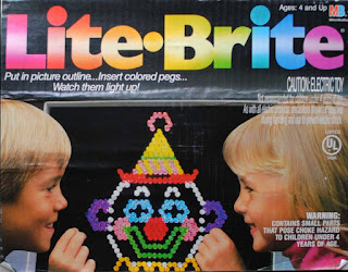
I say perfect... at the moment it looks like a Lite-Brite, not quite the effect I wanted. I needed some diffusion.
I settled on tracing paper and smoked acrylic. The tracing paper smooths out the light and helps to blend the colour from each individual led, and the acrylic hides any black pixels and really makes the image 'pop'.
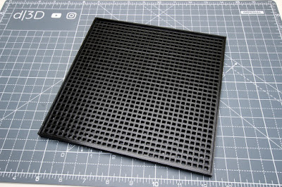
I designed a frame that I could 3D print. It would fit over the LEDs and allow the paper/acrylic to sit on top.
Fusion 360 was a bit sluggish after I set the parameters for the grid, and that made me realise 32 x 32 is 1024(!)
It didn't really occur to me, there were 1024 individual LEDs on that panel. That seems like a massive number.
Anyway, I printed the frame, and it took 22 hours! Now this might not seem too long for some 3D printing veterans, but I absolutely hate waiting for long prints to finish, so 22 hours felt like forever to me.
Luckily the LED panel fit really well (I made a small test piece to check my measurements first) and the acrylic only needed a little persuasion to seat properly. This meant I wouldn't have to print it again, thank goodness.
But after assembling everything and testing some images, I noticed some (subtlety) annoying flaws ...
Most of the frame looked great, but up close some of the lines from the 3D print looked a bit rough.
It also occurred to me that it might look better with square pixels. The actual LED packages on the panel are rectangle and I didn't consider when making the design, so the frame ended up with rectangular pixels too :/
I was loath to re-print the whole thing though. Not just because of the time it took, but also the material.
There was over 100g of filament in that frame, it would have been my biggest waste of plastic in a single print!
But just a few days ago I picked up a new 'toy' that I thought could sort out my problems...
I bought a small hobby cutter, just for playing around with, but it'd be a good excuse to give it a workout here.
I'd cut a square mask for the LEDs out of vinyl and overlay it on my 3D-printed grid. This would fix-up the ragged edges, give me square pixels and wouldn't take an entire day to print or waste plastic. Win-win...win.
Except it was more like win-win-win-lose. While it only took 10 minutes for the machine to cut the mask, in order to transfer it to the frame, all of the unwanted vinyl needed to be removed in a process called 'weeding'.
In my case, it was one thousand and twenty four little squares that I had to pick off the sheet by hand!
I'd only cut a few things from vinyl before, so I don't know if there's an easier way to do this part, but I sat down anyway, put on some music, grabbed a 10A blade scalpel and started poking those little squares.
It took around an hour and a half with a few breaks in between and was actually quite cathartic to work on.
I stuck the mask to a sheet of tracing paper and this would be my new diffusion layer to sit behind the acrylic.
In the end, I think it was worth the extra time and effort to fit the vinyl mask. The improvement is subtle, but in the areas where the 3D print was flawed, it cleaned it up nicely and overall I'm really pleased with the result.
If I ever printed the frame again, then I'd make the whole display a bit deeper so that I could increase the pixel size slightly and shrink the black borders between them. It'd look more elegant with thinner lines I think.
At the moment, I just have it randomly cycling though some animations I downloaded from PIXEL.
Super Mario Kart sprites look pretty cool too and are exactly the right size for this 32x32 panel.
In future I might add some more functionality. Web controls to swap the animations, or some kind of 'magic mirror' style information display for social notifications, weather etc. all might be interesting additions.
I'm also trying to resist buying 20 more of those panels to tile into a giant 1:1 LED GameBoy display...
Subscribe to:
Post Comments (Atom)


Hi! Thanks for sharing! This really looks great! I'm planning on doing something similar. I'm a total 3d printer newbie and would liket o check out your 3d printer file for inspiration. Can you please put your 3d printer file up on github, or somewhere?
ReplyDeleteThanks, the frame has some problems that I describe in the blog post, but if you want to check it out, I've shared it here.
DeleteHow beautiful! I'm trying to make one with Pi 3 ... would you have the diagrams? Would you have any tips for connecting the cables?
ReplyDeleteThanks, I don't have any diagrams specifically. I followed the wiring described here.
DeleteBut I'd probably recommend using something like this from Adafruit to make hooking it up a bit easier.
Hey Mike, great article! i'm on my way to reproduce something similar on my side!
ReplyDeleteJust curious but may I ask what's the usb based device youve added to the Pi card ?
Thanks a ton and thanks for sharing
Thanks, that sounds cool. The USB device is just a little wifi adapter. I used a regular old Pi Zero for this which doesn't have built-in wireless like the newer Pi boards.
Delete